
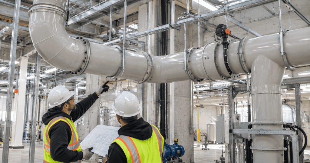
Installation Starts Before the First Duct Section Is Lifted
A fabricated PVC or CPVC exhaust system can arrive on site with the correct material, dimensions, and fittings and still be installed in a way that changes how the system performs. Installation has to preserve the design basis, not just reproduce the route shown on a drawing.
Before field work begins, the installation team should have the latest approved drawings and know which information controls the work. That normally includes duct material, diameters, fitting geometry, support locations, field break points, approved joint methods, equipment interfaces, pressure or vacuum basis, process temperature, and any access or drainage requirements.
This is also the point to reconcile field conditions with the approved layout. Structural steel, platforms, utilities, process equipment, and access routes can shift after design. If a conflict forces a field change, it should be resolved before installers start moving fittings or forcing sections into place.
Verify Delivered Sections Against the Approved Layout
Custom thermoplastic duct systems are often fabricated in sections that depend on sequence and orientation. A reducer turned the wrong way, a branch rotated out of position, or a flange drilled for the wrong mating condition can affect several downstream connections.
Before installation, check the delivered sections against the approved layout and packing information. Confirm section identification, diameter, material, fitting type, branch orientation, flange details, field joint ends, control component orientation, and visible condition after shipping.
Large fabricated sections also deserve a basic geometry check before lifting. Shipping and handling can affect roundness, flange alignment, or fabricated support interfaces. PDI’s Large Diameter PVC Duct resource explains why shipping sections, field assembly, support interfaces, and site access should be considered during fabrication rather than left entirely to the field.
Support the Duct for Its Actual Size, Temperature, and Loads
Support requirements for thermoplastic duct are not one fixed rule. Diameter, operating temperature, material, wall construction, fittings, and concentrated loads all affect the support strategy.
IPEX and Spears publish support guidance that varies with size and temperature. The installation team should therefore use the current manufacturer guidance, project drawings, and construction criteria that apply to the actual system rather than using a generic spacing habit from another material or another project.
Support also means more than hanger spacing. The support should provide adequate bearing area, avoid sharp contact that can damage the duct, and maintain the intended geometry without crushing or distorting the wall.
Detailed support spacing should be verified separately against current manufacturer data, the project design basis, and the actual duct size and operating temperature.
Support Concentrated Loads Directly
Fans, hoods, scrubbers, dampers, large flanges, and other heavy components can create concentrated loads that should not be transferred into the duct wall.
IPEX specifically advises direct support for concentrated loads so that their weight is not transferred into the duct wall as a local stress. That principle matters at equipment interfaces where a rigid component, flange, actuator, or large fitting can otherwise make the duct act like a structural support.
Information
The field team should verify that heavy components are supported independently where required and that their supports do not force the duct out of alignment.
Preserve the Designed Thermal Movement
PVC and CPVC change length as temperature changes. A support system that holds the duct securely still has to respect the movement strategy defined by the design.
IPEX and Spears both treat thermal expansion and contraction as design and installation conditions. Run length, temperature change, anchors, guides, sliding supports, offsets, expansion provisions, and connected equipment all influence where movement goes.
This is why every hanger should not automatically be treated as a rigid restraint. A support may need to carry vertical weight while still allowing axial movement. If a long run is fixed at both ends without a designed movement path, thermal growth can push load into joints, branches, equipment connections, or fabricated transitions.
Before closing out the installation, verify that anchors and guides match the intended arrangement and that movement has not been accidentally blocked by clamps, supports, walls, platforms, or field modifications.
Match Every Field Joint to the Approved Joint Method
PVC and CPVC duct systems can use solvent cement joints, hot gas welded joints, flanged connections, and other project specific details. The correct field method is the one defined by the approved fabrication and installation package.
Spears documents solvent cementing, hot gas welding, and flanged duct connections. IPEX provides detailed solvent cement procedures that address cutting, chamfering, preparation, assembly, push out resistance, excess cement, setting, and cure conditions.
That does not mean every field crew should apply one generic procedure to every joint. Joint geometry, material, diameter, environmental conditions, fabrication method, and project requirements can differ.
Before joining sections, confirm the approved method, required surface preparation, fit, alignment, cure or welding requirements, and inspection criteria. If a field joint is not shown clearly on the approved drawings, resolve it before fabrication assumptions are changed on site.
Do Not Force Fittings and Equipment Connections Into Alignment
A common field temptation is to use the next joint, flange, or fitting to absorb accumulated dimensional error.
That can move stress into the duct wall or joint and can also change fitting geometry. The problem is especially important around reducers, elbows, wyes, tees, dampers, fans, scrubbers, and rigid process equipment.
If two connections do not align naturally, the installation team should determine why before tightening or forcing them together. Do not use heat or mechanical force to make up alignment error unless an approved project procedure specifically permits a controlled field modification. Check support elevations, section sequence, branch rotation, equipment position, and field dimensions.
PDI’s resource on how elbows affect pressure loss shows why fitting geometry matters to system performance. A field adjustment that changes orientation, spacing, or approach conditions may solve a mechanical conflict while creating an airflow problem.
Install Airflow Components in the Orientation the Design Intended
An airflow component can be physically connected and still be installed incorrectly for the system.
Elbows should match the specified orientation and turning direction. Reducers should match the intended upstream and downstream diameters. Wye and tee branches should enter the main in the planned direction. Blast gates and butterfly dampers should remain accessible and installed in the orientation required by their design and operation.
This matters because fittings interact with the airflow entering and leaving them. Closely spaced elbows, reducers, branches, and control devices can change pressure loss and flow distribution.
The installation crew does not need to redesign the system in the field, but it does need to preserve the geometry that the engineer and fabricator designed. When a routing conflict requires a change, the change should be reviewed as a system decision rather than treated as a simple fit issue.
Plan for Condensate, Drainage, and Wet Service
Corrosive exhaust systems may see condensate, wash down liquid, or other wet service conditions. Any specified drainage features, low point provisions, slopes, or access points need to remain functional after installation.
Do not assume that a visually level or convenient field route preserves the original drainage intent. Supports, equipment elevations, and field offsets can create unplanned low points.
Where the design includes drains or deliberate slope, verify them against the approved drawings. Where the process is expected to create condensate but the installation documents do not define how it is handled, raise the issue rather than inventing a field slope.
Local wet exposure can become a separate service condition from the bulk vapor stream, so condensate handling should be verified against the process design rather than assumed from vapor service alone.
Keep Inspection and Commissioning Access Usable
Installation quality includes future access. Blast gates, dampers, field joints, drains, pressure measurement points, inspection locations, and equipment connections should remain reachable after platforms, insulation, utilities, and other trades complete their work.
This is especially important where the system will need balancing or commissioning measurements. PDI’s industrial PVC duct sizing guide emphasizes the importance of defined operating states and commissioning criteria. The field installation should preserve the locations needed to verify those conditions.
A component hidden behind a wall or blocked by another utility may technically be installed, but it can make balancing, maintenance, inspection, or replacement unnecessarily difficult.
Inspect and Test Before Commissioning
Before the system is placed into service, review both joint integrity and the surrounding installation. For solvent cemented joints, applicable cure requirements need to be complete before testing. IPEX calls for visual inspection of assembled joints and leak testing before commissioning. Its PVC ventilation duct guidance also states that PVC, CPVC, PP, and PVDF pipe and fittings must not be tested with compressed air or gas.
For that reason, this article does not prescribe a universal test pressure or test method. Testing should follow the approved project procedure, current manufacturer guidance, applicable code requirements, and the authority having jurisdiction.
The final field review should also confirm supports, alignment, heavy component support, control component operation, equipment connections, drainage provisions, access points, and any approved field changes.
Final PVC Duct Installation Checklist
| Checkpoint | What to Verify | Why It Matters |
|---|---|---|
| Approved drawings | Latest approved revision is available in field | Prevents installation from obsolete geometry |
| Material | PVC or CPVC matches approved schedule | Preserves intended service envelope |
| Supports | Locations and support condition match design | Controls structural loading and duct shape |
| Heavy components | Fans, scrubbers, dampers, and large flanges supported as required | Limits concentrated load on duct |
| Thermal movement | Anchors, guides, and movement provisions preserved | Avoids unintended stress accumulation |
| Field joints | Approved joint method and preparation followed | Maintains joint integrity |
| Fittings | Correct size, orientation, and sequence | Preserves airflow geometry |
| Equipment connections | Alignment achieved without forcing duct | Reduces transferred load and distortion |
| Condensate provisions | Drains, low points, and slope provisions maintained | Preserves wet service intent |
| Access | Dampers, joints, drains, and test points remain reachable | Supports commissioning and maintenance |
| Testing | Approved inspection and test procedure completed | Finds defects before service |
| Documentation | Approved field changes and final conditions recorded | Preserves the installed system record |
The checklist is most useful when it is completed against the actual project drawings rather than treated as a generic sign off form. Any field change that alters geometry, support, joint method, drainage, equipment loading, or access should be documented before commissioning
Installation Quality Should Preserve the Design Basis
A successful PVC duct installation is not defined only by whether every section fits between two points. The installed system should preserve the material service envelope, support strategy, thermal movement, joint integrity, fitting geometry, drainage provisions, equipment interfaces, and commissioning access that the design assumed.
That is particularly important in corrosive exhaust service, where installation stress or a field change can combine with temperature, chemistry, pressure, or condensate later in service.
When installation decisions are made with the complete system in mind, the field work supports the same performance basis that guided duct sizing, fitting selection, fabrication, and fan selection.
Need Help Reviewing an Industrial PVC or CPVC Duct Installation?
Send PDI the approved drawings, duct diameters, PVC or CPVC material, field joint method, support layout, equipment connections, normal and peak temperatures, pressure or vacuum conditions, site constraints, and photographs of the installation area through the Request Information form.
Have your specs ready?
PDI can review fabrication and field interface requirements before custom sections are installed or replaced.