Why Corrosive Duct Failures Are Often Combination Failures
A failed duct section can make the diagnosis look obvious. A joint leaks, a horizontal run sags, a fitting shifts out of alignment, or a surface begins to soften or crack. The visible location is useful evidence, but it is not automatically the root cause.
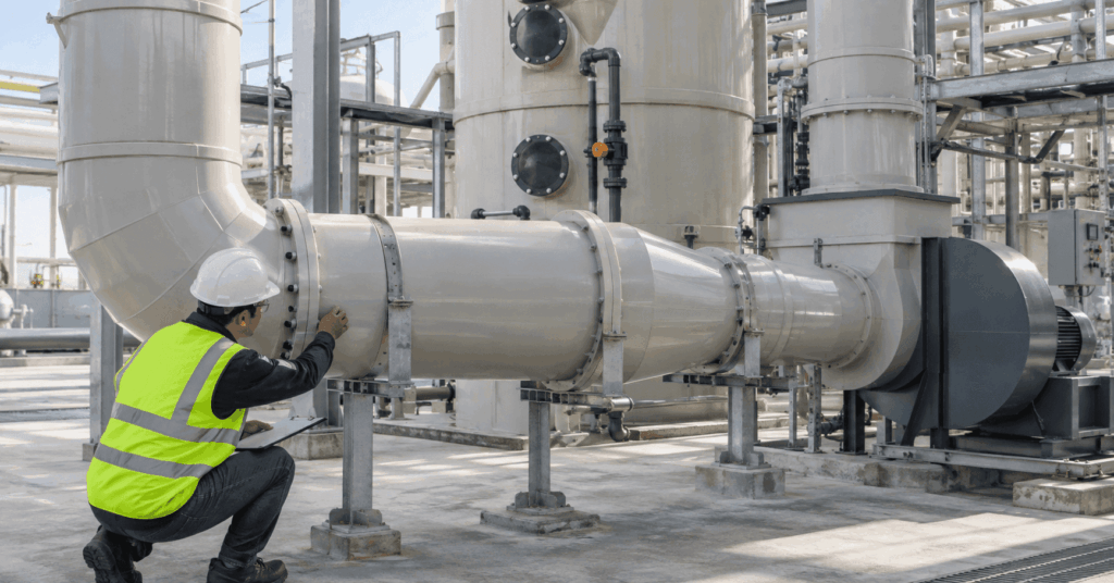
Industrial corrosive exhaust systems carry chemical, thermal, pressure, support, and equipment loads at the same time. A visible failure can therefore originate somewhere else in the assembly.
A credible failure review starts by comparing the original design basis with the conditions the duct actually experienced in service.
Chemical Compatibility Can Change After the System Is Installed
Process changes can alter the chemical condition seen by the duct. New cleaners, higher concentration, mixed exhaust, solvent content, impurities, or a shift from dry vapor to wet exposure all matter. PDI’s PVC Duct Chemical Resistance resource explains why compatibility must follow the actual constituents, concentration, temperature, exposure form, and condensate.
Manufacturer resistance guides are screening tools. IPEX notes that its PVC chemical resistance information includes immersion tests on unstressed coupons, experiments, process experience, and some tests involving temperature and pressure, while actual service conditions can change chemical resistance.
When chemical attack is suspected, compare the current exhaust stream with the original design basis, including cleaners, upset chemistry, condensate, and external products that may contact the duct.
Temperature Excursions Can Remove Structural Margin
Startup peaks, cleaning cycles, loss of dilution air, or one hotter branch can expose a section to temperatures above the main duct average. Spears duct data show that support spacing can change with operating temperature, so supports, diameter, fitting loads, pressure, and thermal movement deserve closer review as temperature rises.
PDI’s PVC Duct Temperature Limits and CPVC Duct Temperature Limits resources cover the ratings in detail. For failure analysis, reconstruct the hottest credible condition at the damaged location rather than relying on the normal operating set point.
Sagging, distortion, or loss of alignment can be consistent with excessive heat, but the same signs can come from poor support or loading. Review temperature history and structural conditions together.
Mechanical Stress Can Turn Chemical Exposure Into Cracking
Corzan documents environmental stress cracking in CPVC as an interaction between chemical exposure and significant mechanical stress. Cracking can therefore appear locally where stress is higher.
This CPVC evidence should not be generalized to every PVC formulation, but it illustrates a useful investigation principle. Chemical compatibility and mechanical loading should be reviewed together where the material is restrained, forced into alignment, externally loaded, or locally stressed.
Stress concentration points can include tight supports, fixed equipment connections, forced field alignment, heavy controls, and poorly accommodated thermal movement.
Information
If cracking is concentrated around supports, joints, flanges, or equipment connections, the review should include both chemistry and the mechanical condition at that location.
Joint Leakage May Be a Symptom, Not the Root Cause
A leaking joint may be a workmanship issue, but it is also a natural location for movement, alignment error, flange load, cure problems, and stress transfer.
Spears identifies solvent cementing, hot gas welding, and flanged connections for PVC and CPVC duct. IPEX’s CPVC ventilation duct submittal calls for leak testing and visual inspection of assembled joints before commissioning.
When a joint fails, review fabrication quality and the surrounding system. Check whether the joint was forced into alignment, whether a nearby component loads the connection, whether a support restricts movement, and whether operating temperature changed.
Rebuilding the same joint without correcting a continuing load simply restores the same weak point.
Thermal Expansion Needs Somewhere to Go
Thermoplastic duct changes length as temperature changes, and IPEX ventilation duct guidance treats thermal expansion and contraction as a design condition.
A restrained long run can push thermal movement into joints, supports, branches, or equipment connections. A support arrangement that works at one temperature may become restrictive as the duct heats and expands.
Document run length, temperature range, anchors, guides, equipment connections, direction changes, and damage location. Then determine whether the installed system can move without concentrating stress.
Large fabricated sections deserve added review because diameter, reinforcement, supports, shipping joints, and field assembly affect how movement is distributed. PDI’s Large Diameter PVC Duct resource covers these fabrication conditions
Condensate Can Create a Local Service Condition
A vapor stream and its condensate should not automatically be treated as the same exposure condition.
Condensate can collect at low points, fittings, and equipment connections. It can remain in contact with the duct longer than the passing vapor and create a local wet exposure condition that differs from the bulk exhaust stream.
Condensate does not automatically cause failure, but the local exposure needs its own review. At a damaged low point, drain, elbow, reducer, or process connection, identify the liquid, exposure duration, chemistry, and temperature.
Pressure and Vacuum Must Match the Actual Duct Construction
Thermoplastic duct should be evaluated using duct construction data, not pressure pipe ratings.
SMACNA’s Thermoplastic Duct Construction Manual provides construction guidance for PVC duct under defined positive and negative pressure classes. Spears states that its round PVC and CPVC duct follows that SMACNA construction approach.
Verify normal static pressure and the maximum credible positive or negative pressure in actual operation. Fan shutoff pressure, closed gates or dampers, process changes, or altered branch configurations can create conditions different from the original design case.
Diameter, wall construction, reinforcement, supports, and fabrication method all matter. Do not assign a custom large diameter section the pressure or vacuum capability of a standard extruded duct product without a project specific basis
Warning Signs Are Clues, Not Diagnoses
The same visible condition can have more than one cause. Use inspection findings to direct the investigation rather than to close it.
- Observed condition: Sagging or loss of roundness. Possible contributors: elevated temperature, long spans, inadequate support, or pressure loading. Verify first: temperature history, support spacing, pressure, and duct construction.
- Observed condition: Cracking near a support or joint. Possible contributors: local stress, forced alignment, thermal movement, or incompatible chemistry. Verify first: support restraint, alignment, chemistry, and temperature.
- Observed condition: Joint leakage. Possible contributors: joint execution, cure, misalignment, movement, or component load. Verify first: joint method, cure record, alignment, nearby loads, and leak history.
- Observed condition: Softened or swollen surface. Possible contributors: chemical incompatibility or solvent and plasticizer exposure. Verify first: chemical identity, concentration, cleaning products, ancillary materials, and temperature.
- Observed condition: Blackening, whitening, surface etching, or blistering. Possible contributors: chemical degradation or service outside recommended temperature, pressure, and concentration conditions. Verify first: chemistry, temperature, concentration, pressure, and external contact.
- Observed condition: Repeated equipment misalignment. Possible contributors: thermal movement, support restraint, or equipment load. Verify first: anchor and guide arrangement, temperature range, and connection detail.
- Observed condition: Recurring liquid at a low point. Possible contributors: condensate, drainage geometry, or liquid chemistry. Verify first: drainage, low points, condensate composition, and exposure duration.
Corzan identifies swelling, distortion, blackening, blistering, surface etching, softening, and cracking as possible signs of CPVC compatibility problems under different exposure conditions. Treat them as clues that must be interpreted with the material, operating history, stress, temperature, concentration, and chemistry.
Do Not Repair the Failure Before Rebuilding the Service History
Before a replacement section is released for fabrication, rebuild the conditions that existed at the failure location.
- Process chemicals and concentration range.
- Cleaning chemicals and external chemical exposure.
- Normal operating temperature.
- Highest credible process, cleaning, or upset temperature.
- Presence and composition of condensate.
- Normal system static pressure.
- Maximum credible positive or negative pressure.
- Fan and control device operating states.
- Duct diameter, wall construction, and reinforcement.
- Support locations and support condition.
- Joint method and field assembly details.
- Nearby reducers, dampers, branches, and equipment connections.
- Observed failure location and pattern.
- Maintenance, process change, and operating history.
This information often determines whether the repair should reproduce the original detail or correct the design basis that allowed the failure to develop.
The Replacement Specification Should Correct the Cause
If the original material remains compatible and the failure came from installation stress, support condition, joint execution, or an unaccounted operating state, the material may remain appropriate while the surrounding detail changes.
If chemistry or temperature has moved outside the original service envelope, repeating the same construction may restart the failure cycle. The new specification may require another material, revised geometry, different supports, improved drainage, or a changed connection detail.
PDI fabricates corrosion resistant PVC and CPVC duct systems, including fabricated reducers, butterfly dampers, and custom components. A replacement should be based on the actual process condition, not only the dimensions of the failed part.
A failure investigation should end with an updated specification, not only a repair sketch.
Need Help Reviewing a Failed Corrosive Exhaust Duct Section?
Send PDI the process chemistry, concentration, normal and peak temperatures, duct diameter, pressure or vacuum conditions, photographs of the affected area, support arrangement, joint type, and operating history through the Request Information form.
Have your specs ready?
PDI can review the fabrication requirements and help identify the information needed before a replacement section is produced.