
In Exhaust Service, Branch Flow Usually Converges
In many industrial exhaust networks, branch fittings combine air collected from separate hoods, tanks, tools, enclosures, or process connections into a larger main that continues toward a fan, scrubber, collector, or discharge point.
That makes the branch a converging junction. The branch stream enters an existing main stream, and the two flows must combine into the downstream duct. The pressure consequence depends on how those streams meet, not only on the nominal branch size.
This distinction matters because much of the generic discussion around wyes and tees comes from residential supply systems or simple dust collection layouts. Industrial exhaust design has a different priority: preserve the required capture airflow while controlling system resistance across every credible operating condition.
Branch Angle Changes How the Air Streams Meet
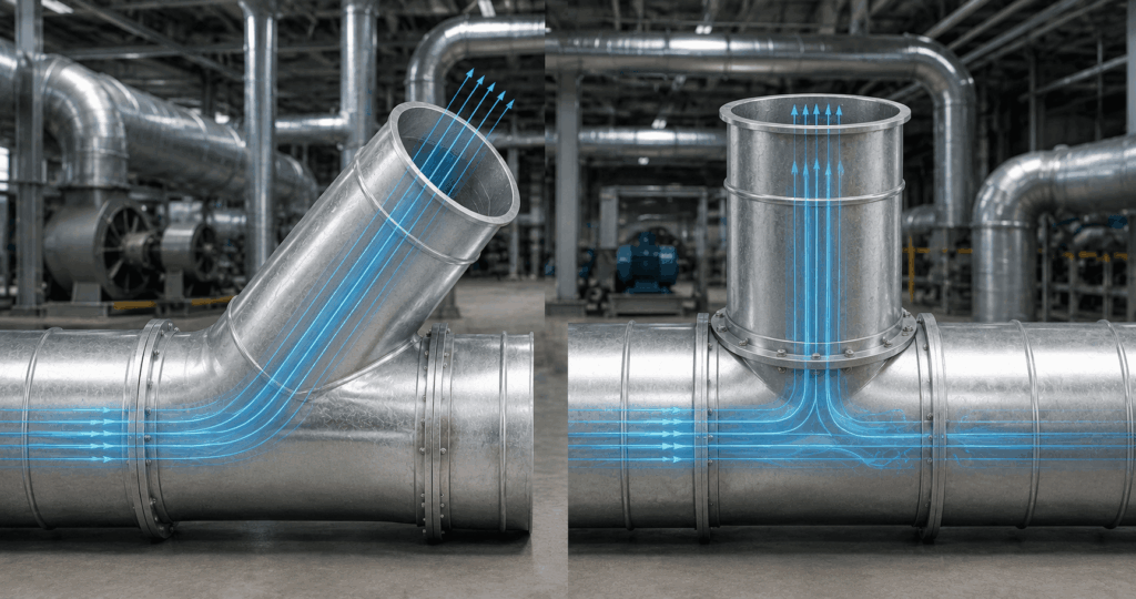
A 45° wye introduces the branch flow at an angle that more closely follows the direction of the downstream main. A 90° tee introduces the branch perpendicular to the main. Those geometries create different momentum changes and different mixing conditions inside the junction.
A more gradual entry can reduce the severity of the direction change, but branch angle by itself does not determine the installed pressure loss. The result also depends on branch velocity, main velocity, the relative airflow in each stream, the ratio of branch area to main area, and the condition of the flow entering the fitting.
This is why a fitting should not be selected from geometry alone. A 45° wye can be an efficient junction, but it is not automatically the lowest loss choice in every layout. Likewise, a 90° tee is not automatically poor practice simply because the branch enters at a right angle.
Pressure Loss Cannot Be Assigned From the Fitting Name Alone
ASHRAE does not assign one universal pressure loss value to every tee or wye. Its Duct Fitting Database provides fitting specific loss coefficients, and the 2025 ASHRAE Handbook duct design chapter shows industrial exhaust wyes evaluated with defined flow ratios, area ratios, and separate coefficients for the main and branch flow paths.
For an exhaust branch, the engineer therefore needs to define the path and operating condition being evaluated. In the 2025 ASHRAE industrial exhaust example, the same 30° wye is assigned different coefficients for the main and branch paths because the flow and area relationships differ. That is the level of specificity a branch calculation requires.
Ask a sharper question.
Not just “what is the loss of a tee?” but “what coefficient applies to this branch geometry, flow ratio, area ratio, and reference velocity under the operating condition being evaluated?”
That level of definition is especially important when several branches accumulate along a common main. Small assumptions at individual junctions can affect the controlling pressure path and the fan duty once the complete network is assembled.
Why a 45° Wye Often Works Well in Industrial Exhaust
A 45° wye is a strong option when the layout benefits from an angled branch entry and provides enough longitudinal space for the fitting. The geometry gives the entering stream a more gradual change in direction and can reduce the disturbance created as the branch joins the main.
PDI’s engineered PVC and CPVC duct systems include fabricated 45° Wye Branch fittings for industrial service. In a properly sized exhaust network, that fitting can be particularly useful where several process branches combine into a main and the designer wants to limit unnecessary junction resistance.
A wye can also simplify the routing when the branch already approaches the main from an angle. In that case, forcing the branch into a perpendicular tee may require an additional elbow before the junction. The pressure comparison should then include the complete route, not just the branch fitting by itself.
The same principle applies to space. A 45° wye typically needs more longitudinal room than a perpendicular tee. If creating that room forces a longer route, extra turns, difficult supports, or a poor equipment connection, the apparent aerodynamic advantage may be reduced or lost.
When a 90° Tee Can Be the Correct Fitting
A 90° Tee Branch can be the practical choice where equipment connects perpendicular to the main, where the available footprint is tight, or where a retrofit must tie into an existing duct run without creating additional offsets.
PDI fabricates 90° Tee Branch fittings in PVC and CPVC for industrial ventilation service. The tee should be treated as a defined junction in the pressure model rather than rejected by rule of thumb.
A tee may still be the better overall layout when the perpendicular approach avoids extra fittings, matches the equipment connection, or is supported by fitting data for the actual geometry and operating condition. In those cases, the complete route may be more practical even though the individual branch entry is less gradual than a wye.
The specification consequence is straightforward: do not select a tee because it is compact and then ignore its loss. Include the appropriate junction coefficient in the system model and verify that the resulting branch airflow remains acceptable at the fan operating point.
Flow Ratio Can Change the Answer
Consider two branches with the same nominal fitting geometry. In the first, the branch adds a relatively small airflow to a much larger main. In the second, the branch airflow is close to the airflow already moving through the main before the junction.
Those two junctions do not create the same flow interaction. The relative momentum of the streams is different, the downstream velocity field can be different, and the applicable loss coefficients can change.
This is one reason published junction data are organized around flow ratios and area ratios rather than a single number for every fitting. It is also why a branch should not be released for fabrication based only on nominal diameters and angle.
If the system has multiple operating modes, the relevant flow ratio may also change. A branch that is minor when every hood is active can become dominant when nearby branches are closed or throttled. The fitting still has the same shape, but the aerodynamic condition at the junction has changed.
Do Not Evaluate the Junction in Isolation
A branch fitting rarely sits in a perfect length of straight duct with fully developed flow on every side. An elbow may be immediately upstream. A reducer may follow the junction. A blast gate or damper may change the branch condition. A fan inlet may be only a short distance downstream.
These adjacent components matter because the velocity profile entering the junction may already be distorted. PDI’s resource on how elbows affect pressure loss explains why closely spaced fittings and fan proximity can create effects that are not represented well by treating every component as isolated.
The same caution applies to wyes and tees. A well selected wye can still perform poorly if the branch enters directly after a tight elbow. A tee can become more consequential if it is followed immediately by another major change in geometry. Good fitting selection starts with the complete route.
Branch Selection Also Affects Balancing
Branch geometry belongs in the same system model used to establish duct sizes and fan duty. The design airflow for each branch, the pressure required to maintain capture, and the resistance of the controlling path all interact.
PDI’s guide to industrial PVC duct sizing addresses that broader relationship. Changing a branch diameter changes velocity. Changing velocity changes velocity pressure. Changing the branch junction changes the local loss. Changing one branch resistance can alter how airflow distributes through the rest of the network.
That becomes particularly important where blast gates or dampers are used to isolate, regulate, or commission branches. The fitting itself does not balance the system. Its resistance becomes one part of the pressure network that the designer must coordinate with the airflow control strategy.
For systems with several operating states, the branch selection should therefore be checked against the relevant combinations of open and closed branches, not only the all open condition.
Process Conditions Can Change the Practical Choice
Industrial PVC and CPVC exhaust systems also carry process constraints that do not appear in a generic HVAC comparison.
Corrosive vapor, condensate, mist, particulate where applicable, process temperature, cleaning chemistry, and access requirements can affect the preferred layout. A branch may need to avoid a low point that traps liquid. A junction may need access for inspection. A connection near process equipment may need enough clearance for removal or maintenance.
Material suitability remains a separate decision from aerodynamic geometry. Selecting a wye does not extend the temperature or chemical limits of PVC, and selecting a tee does not change the service envelope of CPVC. The branch configuration has to work within the material, structural, and process requirements of the complete duct system.
For larger or unusual junctions, PDI’s large diameter PVC duct and custom fabrication resource explains why geometry, reinforcement, support, shipping, and field assembly may become part of the fitting decision.
Wye vs Tee Selection Factors
| Design consideration | 45° Wye Branch | 90° Tee Branch | What to verify |
|---|---|---|---|
| Branch entry | More gradual angled entry | Perpendicular entry | Actual approach direction and junction geometry |
| Junction loss | Can be favorable where angled entry suits flow | Can impose greater branch turning | Applicable coefficient for actual flow and area ratios |
| Footprint | Needs more longitudinal space | More compact along main | Available layout and equipment clearances |
| Branch airflow ratio | Coefficient varies with flow ratio | Coefficient varies with flow ratio | Branch airflow versus combined downstream airflow |
| Retrofit geometry | May require rerouting to achieve angle | Often suits existing perpendicular connections | Existing equipment and duct alignment |
| Adjacent fittings | Coordinate upstream and downstream geometry | Coordinate upstream and downstream geometry | Elbows, reducers, controls, and available straight length |
| Fabrication | Standard or custom configuration | Standard or custom configuration | Size, material, connections, supports, and access |
The table is a screening tool, not a substitute for fitting data. The final choice should be checked using the pressure loss method and operating conditions used for the rest of the exhaust system.
What Should Be Defined Before a Branch Fitting Is Fabricated?
For a pressure sensitive industrial exhaust system, define:
- Main duct diameter before and after the junction.
- Branch duct diameter.
- Branch angle and approach direction.
- Airflow in the main before the junction.
- Airflow in the branch.
- Combined airflow downstream.
- Velocity in each relevant duct section.
- Flow ratio and area ratio used for the loss calculation.
- Loss coefficient source and reference velocity.
- Normal operating modes and credible alternate operating states.
- Nearby elbows, reducers, gates, dampers, or equipment connections.
- PVC or CPVC material selection.
- Normal and peak process temperature.
- Relevant process chemistry and condensate conditions.
- Maximum positive or negative static pressure where applicable.
- Support, reinforcement, access, and field installation constraints.
This information gives the fabricator enough context to treat the branch as part of an engineered exhaust path rather than as a nominal fitting placed into a drawing after the airflow model is complete.
The Best Branch Fitting Is the One That Fits the Complete System
A 45° wye often provides a more gradual aerodynamic entry. A 90° tee often provides the more compact perpendicular connection. Neither statement is enough to make the specification.
Experienced designers compare the branch within the full pressure network. They look at airflow ratio, area ratio, fitting coefficient, operating state, adjacent geometry, available space, process conditions, supports, fabrication, and maintenance access before deciding which configuration is better.
That is the useful distinction between wye versus tee selection in industrial exhaust work. The fitting should support the required airflow without creating unnecessary resistance or unnecessary complexity elsewhere in the system.
Need a PVC or CPVC Branch Configuration Reviewed?
Send PDI the branch airflow, main airflow, duct diameters, proposed branch angle, routing, fan information, process chemistry, normal and peak temperatures, and expected pressure or vacuum conditions through the Request Information form. PDI can review the PVC or CPVC fitting configuration and help identify whether a standard 45° wye, 90° tee, or custom fabricated branch better fits the application.