

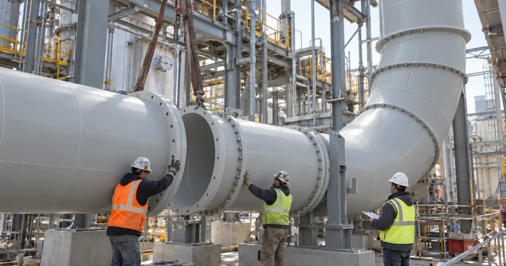
Field Joints Begin as a Constructability Decision
A field joint is not simply a connection added because a duct run became too long for the shop.
In a large custom PVC exhaust system, the joint location affects fabrication, shipping, lifting, alignment, support placement, thermal movement, inspection, and the amount of work that must be completed inside the facility. The joint should therefore be treated as part of the engineered assembly plan.
PDI’s Large Diameter PVC Duct resource explains why custom duct often has to be divided into transportable sections. The next question is where those sections should end and how they will be joined after they arrive at the site.
A fully assembled section may be easy to fabricate accurately in the shop but impossible to move through a plant doorway, roof opening, service corridor, or congested equipment area. The opposite problem can also occur. Breaking an assembly into too many pieces can create unnecessary field work, alignment risk, and quality control demands.
The best field joint location is therefore not defined by one standard length. It is defined by the complete path from the fabrication floor to the final installed position.
Plan Shipping Sections Before Fabrication Drawings Are Locked
Shipping and installation limits should be established early enough to influence the fabrication drawing.
The project team should confirm the maximum practical section length, diameter, width, height, and weight for transport. The review should also include truck loading, site delivery access, unloading area, crane or lift capacity, building openings, elevator or hoist limits where applicable, and the route from the receiving point to the installed location.
A section that fits on the truck may still be impossible to rotate through a mechanical room. A large elbow may fit through an opening but leave no room to align the next straight section. A reducer may be transportable but difficult to support during field assembly.
For those reasons, shipping sections should be drawn as actual installation assemblies, not treated as packaging decisions after fabrication is complete.
Field Joint Locations Should Follow the Installation Sequence
The installation sequence changes what makes a good joint location.
A connection placed in open floor space may be easy to assemble before adjacent equipment is installed. The same connection may become nearly inaccessible after a scrubber, fan, platform, or pipe rack is in place.
Each planned field joint should be reviewed for:
- Access to the full circumference of the joint.
- Space for the joining process and required tools.
- Room for temporary alignment and rigging.
- Ability to support both sections during assembly.
- Clearance for bolts where flanges are used.
- Access for visual inspection after assembly.
- Access for future maintenance where the joint is intended to remain serviceable.
A joint should not be positioned only because it divides the shop assembly conveniently. The field crew has to be able to reach, align, join, and inspect it under the actual installation conditions.
The Joining Method Must Be Defined Before the Joint Is Located
PVC and CPVC duct can be joined using different methods, and those methods create different field requirements.
Spears identifies solvent cementing, thermal hot air welding, and flanged connections among the common joining techniques for its duct systems. The appropriate method depends on the actual duct construction, fitting geometry, material, project specification, service conditions, and whether future disassembly is required.
For large custom fabricated duct, the connection method should be specified before the joint location is finalized because the required working space can vary substantially.
A flanged joint needs access for gasket placement, alignment, bolts, and tightening. A hot gas welded joint needs access for the trained welder to work around the connection and maintain the required welding angle and control. A socket connection needs sufficient engagement and an approved solvent cementing procedure.
The connection geometry and the installation access should be designed together.
Solvent Cement Joints Need the Correct Connection Geometry
Solvent cementing is common in thermoplastic systems, but it should not be treated as a universal way to join any two cut duct ends.
Spears states that its typical duct fittings use belled end sockets for solvent cement joining and specifies a minimum socket depth of 3 inches for its duct system. It also states that extra care is required on diameters 18 inches and larger and that solvent cement should not be used for end to end joining.
Those details are manufacturer specific, but the engineering lesson is broader. A field solvent cement joint needs a connection specifically designed for solvent cement assembly. Two plain fabricated ends should not be assumed to form a valid solvent cement field joint.
The project should also use the primer, cement, cure procedure, surface preparation, fit, and environmental limits required for the actual material and joining system. Cure time should not be copied from a generic chart without considering size, temperature, humidity, cement formulation, and manufacturer instructions.
Hot Gas Welding Requires Access and Qualified Personnel
Hot gas welding can be useful where fabricated thermoplastic sections need a welded connection, but it changes the field planning requirements.
Spears describes thermal welding as a process in which clean hot air heats the duct material and welding rod while pressure is applied to form the weld. It also specifies that welding rod should match the material being joined and that personnel performing PVC or CPVC hot air welding should be specifically trained.
A field welded joint therefore needs more than physical clearance between duct sections.
The layout should allow the welder to access the required weld area safely and consistently. Temporary supports should hold the sections in alignment without forcing the joint together. The work area should also fit the project requirements for surface preparation, environmental control, inspection, and protection from other construction activity.
A field weld should not be expected to correct a dimensional mismatch that should have been resolved during fabrication or fit planning.
Flanged Joints Can Improve Assembly Access but Still Need Engineering
Flanged connections are often attractive at field assembly points because they can simplify installation and allow later disassembly.
That does not make every flange location interchangeable.
The project should define flange construction, gasket material, bolt pattern, hardware, tightening procedure, alignment tolerance, and service compatibility for the actual system. The joint should also have enough surrounding space for installers to place the gasket, insert and tighten fasteners, and visually verify the assembled connection.
Flanges can add local weight and stiffness. Large flanged connections may therefore influence support placement, especially when they occur near reducers, elbows, dampers, equipment transitions, or other heavy components.
A flanged field joint should be coordinated with the support plan rather than suspended between supports as an afterthought.
Field Joints Should Not Become Accidental Structural Weak Points
The duct section on each side of a field joint needs to be supported through the assembly process and in final service.
IPEX and Spears both emphasize support, bearing area, concentrated loads, and thermal movement in thermoplastic duct systems. Those principles become especially important when a large fabricated assembly is divided into field sections.
A joint located far from a support may experience alignment difficulty during installation or unnecessary bending load after startup. A support placed too close to a joint may interfere with welding, bolting, or inspection. A heavy fitting beside the joint can further change the load path.
The support design should therefore answer two different questions:
How will the sections be held in alignment while the field joint is made?
How will the completed assembly be supported during operation?
Temporary rigging is not the final support system. Final supports should be shown on the installation drawings and coordinated with the field joint geometry.
Do Not Use Heat or Force to Correct Poor Field Alignment
Large thermoplastic sections can be difficult to align when structural openings, equipment connections, and supports are not exactly where the fabrication drawing assumed.
The solution should not be uncontrolled heating, excessive pulling, or forcing the duct into position.
If the field geometry does not match the fabricated assembly, the discrepancy should be measured and reviewed. The corrective action may involve support adjustment, a revised spool, a custom transition, or another approved modification.
Any controlled thermal forming or field modification should be performed only when it is part of an approved fabrication or installation procedure.
Forcing the connection together can introduce residual load into the joint, adjacent fittings, supports, or equipment interfaces. The joint may appear complete while the system is carrying a load that was never intended in the design.
Field Joint Planning Must Include Thermal Movement
A field joint and an expansion joint are not automatically the same thing.
PVC and CPVC change length as temperature changes. PDI’s thermal expansion resource explains that supports, guides, anchors, offsets, and expansion components have different functions in controlling that movement.
A flanged connection may be removable without being intended to accommodate axial expansion. A welded connection may be structurally continuous but still sit within a run that must move relative to its supports.
The design should therefore identify which joints are simply assembly connections and which components, if any, are intended to accommodate thermal movement.
Anchor locations, guide locations, equipment interfaces, and movement allowances should be coordinated before field joint locations are finalized.
Pressure and Vacuum Still Apply Across the Field Joint
Breaking a duct system into shipping sections does not change the operating differential pressure the completed assembly must withstand.
The field connection should be suitable for the same design operating conditions as the surrounding duct, including the maximum credible positive or negative differential pressure.
That review can include normal fan operation, fan shutoff pressure where applicable, closed gates or dampers, process changes, and altered branch configurations that affect system pressure.
Do not transfer pressure ratings from pressure pipe to fabricated duct or assume that a connection is acceptable simply because it is made from the same material. The joint construction has to fit the duct design basis.
Spears classifies fabricated duct fittings as non pressure rated and notes that custom fabricated products are made to user specification. That is one reason custom field connections should be defined from project conditions rather than from a generic pipe rating.
Fittings and Equipment Interfaces Can Determine the Best Joint Location
The most convenient straight section is not always the best place for a field joint.
Large elbows, reducers, wyes, tees, blast gates, dampers, scrubber connections, and fan transitions can control how the system has to be shipped and assembled.
A large reducer may be easier to ship separately but difficult to align at the equipment nozzle without temporary support. A large elbow may need to be installed before an adjacent straight run because the available rotation space disappears later. A branch assembly may require the main duct to be positioned before the branch connection can be completed.
The field joint plan should therefore be developed from the assembly sequence around major fittings and equipment, not from straight duct length alone.
Quality Control Should Be Defined Before Field Work Starts
A field joint should have an acceptance process before the installer begins work.
The project documentation should identify the approved joining method, material, surface preparation, alignment requirements, personnel qualifications where applicable, cure or cooling requirements, gasket or hardware requirements, and inspection method.
Useful Information
For fabricated thermoplastic duct, the exact acceptance criteria should come from the project specification, fabricator requirements, manufacturer guidance, applicable code, and authority having jurisdiction where relevant.
IPEX requires its ventilation duct installation to be visually inspected and leak tested after installation and joint cure under the applicable project and code requirements. IPEX also warns that the listed PVC, CPVC, PP, and PVDF pipe and fittings must not be tested with compressed air or gas.
That warning should not be turned into a universal statement about every custom fabricated PDI duct assembly. The test method for a custom system should be established by the approved project procedure.
The important planning point is that inspection and testing access must exist after the field joint is complete.
A Field Joint Schedule Can Prevent Installation Problems
For complex projects, field joints should be identified directly on the fabrication and installation drawings.
A useful field joint schedule can record:
- Joint identification number.
- Duct size and construction.
- Connection method.
- Shop section on each side of the joint.
- Installed elevation and orientation.
- Required access around the joint.
- Temporary support or rigging requirement.
- Final support locations.
- Nearby fitting or equipment interface.
- Thermal movement function, if any.
- Joining procedure reference.
- Inspection requirement.
- Testing requirement.
- Installation sequence note.
This turns field joints into controlled project interfaces rather than improvised connection points.
What Must Be Confirmed Before Fabrication Release
Before a large PVC duct system is released for fabrication, the project team should confirm:
- Maximum shipping section dimensions and weights.
- Site delivery and unloading limits.
- Route from receiving area to installed location.
- Building openings and access restrictions.
- Crane, lift, or rigging limitations.
- Joint locations shown on fabrication drawings.
- Approved connection method at every field joint.
- Required access for solvent cementing, welding, or flange assembly.
- Temporary alignment and support method.
- Final support locations around the joint.
- Major elbows, reducers, branches, dampers, and equipment interfaces.
- Thermal movement strategy.
- Normal and maximum credible pressure or vacuum.
- Material compatibility for duct, welding rod, gaskets, and other connection materials.
- Field personnel qualification requirements.
- Inspection and approved leak test requirements.
- Sequence of installation relative to adjacent equipment and structures.
These decisions are easier and less expensive to make before fabrication than after a large custom assembly reaches the job site.
Field Assembly Should Be Designed, Not Improvised
The strongest field joint plan begins with a simple principle: shop fabrication, transport, rigging, field assembly, and final operation are parts of the same system.
A joint that is easy to fabricate but impossible to access is not a good joint. A connection that is easy to assemble but poorly supported is not a good joint. A flange that fits the installation sequence but conflicts with thermal movement or process chemistry is not a good joint.
For large PVC exhaust systems, field joints should be placed where the sections can be transported, supported, aligned, joined, inspected, and operated as intended.
That planning belongs in the fabrication package before the first oversized section leaves the shop.
Need Help Planning a Large PVC Duct Assembly?
Send PDI the duct sizes, layout, process chemistry, temperatures, pressure or vacuum conditions, fitting locations, equipment interfaces, shipping limits, site access constraints, and proposed installation sequence through the Request Information form.
Have your specs ready?
PDI can review the fabrication breakdown and help coordinate custom sections and field joint locations before fabrication begins.