

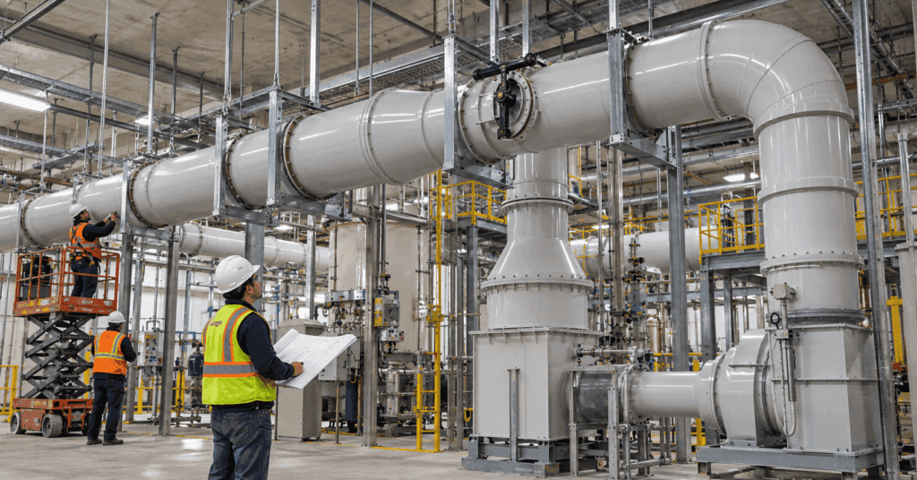
PVC Duct Support Spacing Is Not One Fixed Number
A support spacing value only has meaning when it is tied to a specific duct construction, diameter, material, temperature, and loading condition. That is why published thermoplastic duct tables should be read as product data, not as a universal rule for every PVC exhaust system.
For standard ventilation duct, manufacturers such as IPEX and Spears publish maximum horizontal support spacing values by nominal diameter and operating temperature. Those tables are useful because they show two things immediately. First, allowable span can change as temperature rises. Second, diameter does not create one simple progression where every larger duct automatically needs closer supports.
Support spacing should therefore be selected from the product data that applies to the actual duct construction and operating condition, then reviewed for loads or installation details that require additional support.
Temperature Can Reduce the Allowable Horizontal Span
IPEX’s Vinyl Process Piping Systems manual lists PVC modulus of elasticity at about 400,000 psi at 73°F and 280,000 psi at 140°F. That loss of stiffness is one reason support spacing has to be checked at the operating temperature that governs the run, not only at room temperature.
IPEX publishes recommended maximum horizontal support spacing for air filled PVC ventilation duct at several temperatures. The values below are selected examples from that specific standard product table.
| IPEX PVC Duct Size | 73°F | 100°F | 140°F |
|---|---|---|---|
| 6 inch | 10 ft | 9 ft | 6.5 ft |
| 12 inch | 12 ft | 12 ft | 9.5 ft |
| 24 inch | 12 ft | 12 ft | 12 ft |
These are selected manufacturer examples, not a universal PDI support table. They show why temperature belongs in the support decision. For the 6 inch product, the published maximum decreases from 10 feet at 73°F to 9 feet at 100°F and 6.5 feet at 140°F. The same table lists 12 inch duct at 12 feet through 100°F, then 9.5 feet at 140°F.
The 24 inch value remains 12 feet across the published temperature range in that particular IPEX table. That does not mean all 24 inch PVC duct can be supported at 12 feet. It means that IPEX publishes that value for its specified air filled PVC ventilation duct construction under the conditions represented by the table.
Spears publishes a very similar PVC ventilation duct table and states that its maximum horizontal support spacing values are based on air filled duct with an allowable 1/8 inch deflection at the listed temperatures. This is useful context because the spacing value is tied to an explicit deflection basis, not simply to what looks acceptable in the field.
Diameter Does Not Create a Simple Spacing Rule
It is tempting to assume that increasing diameter should always reduce the allowable span because the duct becomes larger. Published ventilation duct data show why that shortcut is unreliable.
Across a standard product line, diameter, wall construction, section geometry, and structural behavior do not stay constant while only size changes. The manufacturer table reflects the actual product construction for each listed diameter. That is why the correct value must be taken from the applicable row and temperature column instead of extrapolated from a smaller size.
Information
This also means engineers should be cautious when moving from one manufacturer, one duct series, or one fabrication method to another. A spacing value for one standard product is not automatically transferable to a different construction just because the nominal diameter matches.
Use Manufacturer Tables as Product Data, Not Universal Design Rules
Three boundaries matter when using a support table.
First, verify that the table is for ventilation duct, not pressure pipe. Pipe support data and ventilation duct support data are not interchangeable simply because both products are PVC.
Second, verify that the material and temperature range match the project. PDI’s PVC Duct Temperature Limits and CPVC Duct Temperature Limits resources cover the material service boundaries separately. PVC and CPVC also have different published support tables. IPEX, for example, publishes CPVC ventilation duct values through 200°F. For 6 inch CPVC duct, the published maximum remains 10 feet through 160°F and decreases to 8 feet at 180°F and 200°F. For 16 inch CPVC duct, the same table publishes 12 feet through 160°F and 10 feet at 180°F and 200°F.
Third, confirm that the duct is actually the standard product represented by the table. A custom fabricated section, unusual wall construction, reinforced assembly, rectangular transition, manifold, equipment connection, or oversize duct may need a separate structural review.
Concentrated Loads Need Their Own Support
A straight duct span and a concentrated component are different structural conditions.
IPEX and Spears both call for additional consideration where components place concentrated weight into the system. Typical examples include fans, hoods, scrubbers, dampers, large flanges, tanks, flexible connections, and other equipment interfaces. Spears specifically states that these system components should receive independent support where needed so their weight does not become a local duct load.
This matters directly to fabricated exhaust systems. A butterfly damper or blast gate may match the duct diameter but still introduce a concentrated component load at one location. A large reducer can change the load path around a transition. A rigid fan or scrubber connection can transfer alignment forces into the duct if the equipment support and duct support are not coordinated.
The support layout should therefore identify where concentrated loads occur instead of assuming that regular hanger spacing alone will carry every component.
Accumulated Solids and Condensate Can Change the Load
The IPEX and Spears spacing tables cited here are for air filled ventilation duct. That assumption matters.
Spears instructs designers to consider additional weight from accumulated solids and calls for inspection, cleaning, and maintenance to prevent added loads from developing in service. It also requires drains where moisture accumulation is expected and at low points defined on the system drawings.
For corrosive exhaust, a run that normally carries vapor may still experience condensate or liquid accumulation at low points, process connections, or drainage locations. The support design should account for credible added weight where the process can produce it. It should not assume that every section will remain dry and empty simply because the primary service is exhaust air.
This is also why the support review and condensate review should agree with each other. A drainage provision that moves liquid toward a low point can create a local load condition that deserves deliberate support.
A Hanger Must Support the Duct Without Damaging It
Support spacing is only one part of support quality. The hanger itself has to carry the duct without creating local damage or unintended restraint.
IPEX advises that hangers provide as much bearing surface as possible and warns against sharp supports or sharp edges that can damage the duct as it moves. Spears similarly requires adequate load bearing surface, smooth contact, proper alignment, and hanger materials suitable for the corrosive environment.
That leads to several practical checks. The support should not create a narrow point load. Hardware should not cut into or distort the duct wall. The hanger should hold the run in uniform alignment. Over tightening should be avoided where it would deform the duct or restrict intended axial movement.
In an industrial environment, hanger and hardware material also need to suit the surrounding atmosphere. A corrosion resistant duct system can still develop a support problem if the hardware itself is not appropriate for the service environment.
Plan for Condensate, Drainage, and Wet Service
Corrosive exhaust systems may see condensate, wash down liquid, or other wet service conditions. Any specified drainage features, low point provisions, slopes, or access points need to remain functional after installation.
Do not assume that a visually level or convenient field route preserves the original drainage intent. Supports, equipment elevations, and field offsets can create unplanned low points.
Where the design includes drains or deliberate slope, verify them against the approved drawings. Where the process is expected to create condensate but the installation documents do not define how it is handled, raise the issue rather than inventing a field slope.
Local wet exposure can become a separate service condition from the bulk vapor stream, so condensate handling should be verified against the process design rather than assumed from vapor service alone.
Support and Thermal Movement Must Work Together
A hanger can carry vertical weight and still allow axial movement. Those two functions should not be confused.
PVC and CPVC expand and contract as temperature changes. Both IPEX and Spears state that support arrangements should allow the movement intended by the design. A support that is tightened as though every hanger were an anchor can block that movement and redirect load into joints, branches, fittings, or equipment connections.
The support plan therefore has to distinguish among ordinary supports, guides, anchors, and any dedicated expansion provisions. The detailed movement calculation belongs in the thermal expansion design, but the support spacing review should confirm that the chosen hanger arrangement does not defeat that movement strategy.
This is particularly important on long straight runs, outdoor systems, and process exhaust systems with meaningful temperature change between installation and operation.
Standard Duct Tables Do Not Automatically Apply to Oversize Fabrication
That makes 24 inches a useful product range reference for those standard lines, not a universal structural cutoff.
A custom 30 inch or 36 inch duct should not inherit the 24 inch support spacing value simply because it is the next larger size. Custom fabrication may use different wall thickness, reinforcement, joint geometry, fitting construction, and pressure criteria. Those differences can change both stiffness and load distribution.
The same caution applies even below 24 inches when the component is custom fabricated. A large transition, manifold, equipment adapter, saddle connection, or reinforced section may require support locations that are driven by geometry rather than by a straight duct table.
What Engineers Should Define Before Support Spacing Is Finalized
A useful support review needs more than diameter. The design basis should identify:
- Duct material, including PVC or CPVC.
- Nominal diameter and actual construction.
- Standard extruded duct or custom fabricated duct.
- Normal operating temperature and maximum credible temperature.
- Horizontal run length and changes in direction.
- Positive or negative operating pressure where relevant to construction.
- Locations of dampers, blast gates, reducers, flanges, and heavy fittings.
- Connections to fans, scrubbers, hoods, tanks, or other equipment.
- Potential solids, condensate, or liquid accumulation.
- Required drainage locations and low points.
- Anchor, guide, and movement strategy.
- Outdoor exposure, vibration, seismic, or other project specific conditions where applicable.
Once those inputs are known, the support spacing can be selected from the applicable manufacturer data or developed as part of a project specific fabrication and structural review.
Support Spacing Is a Structural Decision, Not a Rule of Thumb
The most reliable support layout is the one tied to the actual duct construction and service condition. Manufacturer tables provide an important starting point for standard PVC and CPVC ventilation duct, but the numbers only apply inside the assumptions behind those tables.
Temperature can reduce allowable span, while diameter does not create a simple linear rule. Heavy components, solids, and liquid accumulation can add load, hanger geometry can either protect or damage the duct, and the support arrangement can preserve thermal movement or accidentally restrain it.
For custom and oversize fabrication, support spacing should be reviewed with the same care as wall construction, pressure, fittings, and field assembly. That keeps the support system aligned with the design basis instead of leaving one of the most important structural decisions to field habit.
Need Help Reviewing PVC or CPVC Duct Support Requirements?
Send PDI the duct material, diameter, construction, normal and maximum temperatures, pressure or vacuum conditions, support locations, equipment connections, concentrated components, expected condensate or solids, and project drawings through the Request Information form.
Have your specs ready?
PDI can review fabrication and support interface requirements for standard and custom duct sections.