
Blast gates are the least glamorous component in an industrial exhaust system and one of the most consequential. They decide which branches pull air, which sit idle, and whether your fan is doing useful work or quietly wasting horsepower on a duct run nobody is using. Specify them badly and you get poor capture at the hood, particulate settling in the ductwork, and a maintenance crew that stops trusting the system.
This guide covers how to select and size blast gates for corrosive industrial exhaust: what they actually do, how they differ from dampers, how to size them without killing transport velocity, and the specification mistakes that show up most often in the field.
What a Blast Gate Actually Does
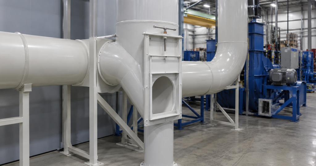
A blast gate is a sliding plate valve. A flat gate travels in a slot across the duct bore, either fully out of the airstream or fully across it. That simple geometry is the whole point. When the gate is open, the bore is unobstructed, so it adds almost no pressure loss to a branch that is running.
In practice, blast gates do three jobs:
- Isolation. Close the branches feeding idle equipment so the fan concentrates its available airflow on the hoods and pickups that are actually in use.
- Sequencing. In a system where several processes share one fan, gates direct suction to whichever process is running.
- Coarse balancing. Gates can trim airflow between branches, though this is the job they do worst, for reasons covered below.
Blast Gate vs. Damper: Not the Same Component
These get conflated constantly, and the confusion produces bad specifications. A blast gate is an on or off device. A damper modulates. They are not interchangeable, and a system usually needs both.
| Factor | Blast Gate | Saddle Blast Gate | Butterfly Damper | Gravity Damper |
|---|---|---|---|---|
| Primary job | Full open or full close of a branch | Same, but mounts onto an existing duct wall | Throttling and airflow modulation | One way backflow prevention |
| Flow control | On or off. Poor at fine throttling | On or off | Proportional across the full range | None. Opens with flow, closes without |
| Obstruction when open | None. Full bore | None. Full bore | Blade and shaft remain in the airstream | Blade remains in the airstream |
| Best used for | Isolating idle branches, directing suction | Retrofits and branch takeoffs on existing runs | Balancing and continuous adjustment | Preventing reverse flow when a fan is off |
| Watch out for | Slot leakage and particulate buildup | Same, plus saddle seal integrity | Permanent pressure loss | Not a control device |
A common and costly error is specifying blast gates where the system actually needs modulating dampers, then discovering during commissioning that the branches cannot be balanced.
Sizing Blast Gates: Match the Duct, Then Check the Velocity
Step 1: Match the nominal duct diameter
Blast gates are sized to the inside diameter of the branch duct they serve. A 6 inch branch takes a 6 inch gate. This sounds obvious, and it is still the most frequently botched step, usually because someone orders to the outside diameter or to a nominal pipe size that does not match the duct schedule in use. Confirm the actual duct ID and the connection method before ordering.
Step 2: Verify that transport velocity is maintained
This is the step engineers skip. Blast gates do not exist in isolation. Closing a gate changes the airflow distribution across the entire system, and the branches that remain open must still carry enough velocity to keep contaminants moving. If velocity drops below the transport minimum, particulate settles inside the duct, and settled material in a corrosive or combustible stream is a maintenance and safety problem. The ACGIH Industrial Ventilation Manual of Recommended Practice for Design is the standard reference for these minimums.
| TECHNICAL SPEC: MINIMUM DUCT TRANSPORT VELOCITY Vapors, gases and smoke: 1,000 to 2,000 FPM. Velocity is set by economics, not by transport. Fumes, including welding fume: 2,000 to 2,500 FPM Very fine light dust: 2,500 to 3,000 FPM Dry dusts and powders: 3,000 to 4,000 FPM Average industrial dust: 3,500 to 4,000 FPM Heavy dusts, such as metal turnings or wet material: 4,000 to 4,500 FPM and above Design note: model the system with the gates in their WORST realistic configuration, not with everything open. The branch that still has to perform when three other gates are shut is the one that governs. Figures are typical published ranges. Confirm against ACGIH for your specific contaminant. |
Step 3: Account for leakage, not just flow
Every slide gate leaks a little at the slot. In a clean air system nobody cares. In corrosive exhaust, leakage means acid vapor escaping into an occupied space, and in a negative pressure system it means unfiltered air being drawn in, which dilutes the stream and steals fan capacity from the branches that need it. Ask for the gate’s leakage characteristics and specify a sealed or gasketed design where the process warrants it.
The Blast Gate Method vs. Balance by Design
There are two accepted ways to balance an industrial exhaust system, and choosing the wrong one is a design level mistake that blast gates cannot fix later.
The blast gate method uses adjustable gates to trim each branch until the system balances. It is flexible and forgiving, and it suits systems where the process changes, branches get added, or only some pickups run at a time.
Balance by design sizes the ductwork itself so that the branches balance naturally at the intended airflow, with no adjustable devices in the run. It is preferred where the material is toxic, explosive, or radioactive, because a balanced system has nothing for an operator to tamper with and nothing to fall out of adjustment.
The practical trade off is this. Blast gates give you flexibility, and they give you something that can be set wrong. Gates get moved by operators chasing better suction at their own station, they get knocked out of position, and the setting nobody documented is the setting nobody can restore. If your system carries a hazardous stream, design the balance in and use gates only for isolation, not for trimming.
Material Selection: The Gate Has to Match the Duct
A PVC duct run with a metal blast gate has a metal blast gate as its failure point. This is the single most common material mistake in corrosive exhaust, and it happens because the duct gets specified carefully and the accessories get treated as commodity hardware.
Blast gates sit in the same acid vapor, the same chloride stream and the same condensing moisture as the duct itself. They need to be fabricated from the same material family. For most corrosive exhaust, that means PVC. Where the stream runs hot, roughly above 140F, it means CPVC. PDI fabricates both blast gates and saddle blast gates in PVC and CPVC to match the duct they serve.
The moving parts deserve the same scrutiny. A gate is only corrosion resistant if the slide plate, the frame, the seals and the fasteners are all rated for the stream. A stainless fastener in a chloride environment will fail long before the PVC body does. For more on matching material to process conditions, see our guide to choosing between PVC, CPVC and FRP duct.
Placement and Access
Where a gate goes matters as much as which gate you buy.
- Locate the gate close to the branch takeoff. A gate set far down the branch leaves a long dead leg between the gate and the main when it is closed, and dead legs collect material.
- Put it in a straight run. A gate installed immediately downstream of an elbow sees disturbed, uneven flow and will not perform as rated.
- Keep it reachable. A gate nobody can get to is a gate that never moves. If the run is high or buried, specify a pneumatic or electric actuator instead of expecting someone to climb to it.
- Provide cleanout access nearby. NFPA 91, the standard for exhaust systems conveying vapors, gases, mists and particulate solids, addresses access and cleanout provisions in exhaust ductwork. Gates are natural accumulation points and should be inspectable.
Manual or Automated?
Manual slide gates are the default and are correct for most systems. They are inexpensive, they have nothing to fail, and an operator can confirm the position by looking at it.
Automated gates, driven pneumatically or electrically, earn their cost in three situations: when the gate is physically inaccessible, when the system has enough branches that manual sequencing becomes unreliable, and when gate position needs to be interlocked with the process equipment so that a machine cannot run with its branch closed. If operators are routinely forgetting to open or close gates, that is not a training problem. That is a specification problem, and automation solves it.
Five Blast Gate Specification Mistakes
- Sizing to pipe size instead of duct ID. Confirm the actual inside diameter and the connection type.
- Modeling the system with all gates open. The governing case is the worst realistic configuration, not the best one.
- Using blast gates to balance a hazardous stream. Design the balance into the duct and use gates for isolation only.
- Specifying a metal gate on a plastic duct run. The accessory becomes the failure point.
- Ignoring the slot. Leakage and particulate buildup at the gate slot are the two things that actually take blast gates out of service.
Frequently Asked Questions
What is a blast gate used for?
A blast gate isolates a branch of an exhaust or dust collection system. Closing the gates on idle branches concentrates the fan’s available airflow on the hoods and pickups that are actually running, which maintains capture velocity where it is needed and prevents the fan from wasting capacity on unused duct.
What is the difference between a blast gate and a damper?
A blast gate is an on or off device. When open, it leaves the duct bore unobstructed, and it is designed to isolate a branch rather than to fine tune airflow. A butterfly damper modulates, holding any position across its range to trim airflow, but its blade and shaft stay in the airstream and add permanent pressure loss. Most systems need both, used for different purposes.
What size blast gate do I need?
Size the gate to the inside diameter of the branch duct it serves, so a 6 inch branch takes a 6 inch gate. Then verify that with the gate closed, the remaining open branches still carry enough velocity to keep contaminants moving. Transport velocity, not the gate itself, is what governs whether the system works.
Specifying Blast Gates for a Corrosive System?
PDI has fabricated PVC and CPVC duct systems and accessories for industrial and laboratory exhaust since 1976. If you are working through gate sizing, material selection, or a retrofit onto an existing run, send us the process conditions and we will help you scope it. Request a quote.