Commissioning Starts With a Defined Test Condition
Commissioning is not simply turning on the fan and confirming that air moves through the duct.
A meaningful commissioning process begins by defining the operating condition that will be tested. The project team should know which hoods, process tools, tanks, enclosures, or branches are expected to operate together, which blast gates or dampers are open, what fan speed applies, what make up air systems are operating, and which airflow or pressure values define acceptable performance.
Without that operating definition, a measured airflow number has little value. A branch may appear low only because another branch is open. A main duct static pressure may look high because the fan is operating at a different speed from the design condition. A system can also pass one operating mode and fail another.
The commissioning record should therefore identify the exact branch states, control positions, fan operating condition, and process mode associated with every important measurement.
Complete a Physical Walkdown Before Startup
The installed duct should be reviewed before the system is placed into normal operation.
This is the point to confirm that the field installation still reflects the approved design. PDI’s PVC Duct Installation Checklist covers the installation process in detail. Commissioning should use that work as a baseline and confirm that no late field change has altered the system.
Check the duct route, sizes, fittings, branch orientation, reducers, elbows, field joints, flanges, blast gates, dampers, drains, supports, and equipment connections against the latest approved drawings.
Look for visible misalignment, unsupported heavy components, contact with structural steel, blocked access, unplanned low points, restrained movement, loose hardware, damaged duct, or field changes that were never incorporated into the final documentation.
A commissioning team should not assume that a system is ready simply because construction is complete.
Verify Supports and Movement Before the Fan Applies Load
Thermoplastic duct support is part of system performance.
IPEX and Spears both publish support guidance for PVC and CPVC duct that varies with size, temperature, and local loading. IPEX also states that concentrated loads such as fans, hoods, scrubbers, dampers, and flanges should be supported directly and that supports should allow intended axial movement where temperature changes occur.
Before startup, verify that the installed support arrangement matches the project requirements and that heavy connected components are not loading the duct wall.
Also check that the thermal movement strategy remains possible. Supports, guides, anchors, offsets, and equipment connections should function as intended. A clamp, wall penetration, platform, or late field modification can unintentionally create a restraint point.
Commissioning is a good time to identify those conditions because the system can then be observed as it moves from the installation temperature toward the operating temperature.
Confirm Joints and Connection Methods
Field joints should match the approved joining method and fabrication details.
PVC and CPVC duct may use solvent cement joints, hot gas welded joints, flanged connections, or other project specific details. The commissioning review should confirm that the installed connection method matches the approved construction and that visible joints are complete, aligned, and accessible for inspection where required.
Do not assume that all thermoplastic joints are equivalent. Joint geometry, material, diameter, fabrication method, cure requirements, welding requirements, gasket selection, and hardware can differ.
Where a field joint has been repaired or modified, the record should identify what changed and which approved procedure was used.
Perform the Required Leak Test Before Commissioning
Leak testing should follow the approved project procedure, manufacturer guidance, applicable code, and authority having jurisdiction.
IPEX states that after its PVC ventilation duct system is installed and solvent weld joints have cured, a leak test should be performed before the system is commissioned. During that test, assembled sections should be visually inspected for joint leaks.
IPEX also warns that the listed PVC, CPVC, PP, and PVDF pipe and fittings must not be tested with compressed air or gas.
That warning should remain scoped to the IPEX products and guidance that state it. It should not be converted into a universal test instruction for every custom fabricated duct system.
For a custom PVC or CPVC exhaust assembly, the approved test method and acceptance criteria should be established by the project specification, fabricator, manufacturer guidance, applicable code, and facility requirements.
Do not invent a field test pressure or leakage limit during commissioning.
Verify Every Blast Gate and Damper Position
A control component can be installed correctly and still be in the wrong operating position.
Before airflow measurements begin, confirm the intended commissioning position of each blast gate, butterfly damper, gravity damper, or other airflow control device.
For manual devices, record the position used during the test. For actuated devices, verify the command and actual position through the approved control sequence.
This matters because branch resistance changes when a gate or damper moves. One device left partly closed can alter airflow throughout a branched system and can change the pressure seen by the fan and other branches.
The commissioning report should make the control state repeatable so a future test can recreate the same operating condition.
Confirm Measurement Locations Before Trusting the Numbers
Airflow measurements are only as useful as the measurement location and method.
PDI’s PVC Duct Sizing resource recommends planning measurement points while the duct layout is still being designed. Straight, accessible locations are generally more useful than trying to obtain representative readings immediately after an elbow, branch, reducer, damper, or equipment connection.
Before testing, verify that the selected airflow and static pressure measurement points are suitable for the approved test method.
The commissioning team should record where each measurement was taken, which operating mode was active, and which branch and control positions applied.
If a measurement location is known to have disturbed flow, the result should not be treated as if it came from an ideal fully developed profile.
Commissioning should make uncertainty visible rather than hiding it behind a precise looking number.
Measure the Airflow the Design Actually Requires
The purpose of airflow verification is to confirm the performance that the design basis requires.
That can include airflow at hoods, tools, enclosures, tanks, branch takeoffs, main ducts, or other process connections. The exact acceptance point depends on the system function.
A commissioning team should not substitute one convenient main duct measurement for all branch requirements unless the design basis specifically allows that approach.
For branched systems, compare the measured distribution with the intended operating state. A main fan can deliver the expected total volume while one critical branch remains short of its requirement.
Where the design includes several operating modes, test the modes that materially change branch interaction or fan duty.
Do Not Confuse Balancing With Fixing a Design Problem
Balancing devices are useful for setting airflow distribution. They are not a substitute for a coherent system design.
If one branch requires extreme throttling while another remains short of airflow, the commissioning team should investigate the pressure path rather than simply continuing to close other branches.
The cause may involve fitting geometry, branch arrangement, unexpected system resistance, incorrect duct size, fan operating point, damper position, equipment pressure drop, or a field change.
A balanced system should still operate within the intended fan and duct conditions.
Commissioning should identify when the final airflow distribution depends on an operating position that is impractical, unstable, or inconsistent with the design intent.
Verify Fan Operating Condition and System Resistance
The duct system and fan have to be evaluated together.
Record the fan operating condition used during commissioning. Depending on the project, that can include fan speed, control command, motor frequency, inlet condition, discharge condition, and reference static pressure.
The measured system resistance should be compared with the design expectation where suitable reference points exist.
A system that requires materially more fan effort than expected may have added resistance from field changes, partially closed components, unexpected equipment loss, poor fitting approach conditions, blocked sections, or another issue.
A system that requires less pressure than expected also deserves review if the airflow is not correct. The objective is not to make the pressure number match a calculation at any cost. The objective is to understand whether the installed fan and duct system are operating at the intended condition.
Check Make Up Air and Building Pressure
Industrial exhaust performance can be affected by the building around it.
If the facility cannot provide enough replacement air, the building pressure can become more negative and the exhaust fan can see a different pressure boundary from the design assumption.
During commissioning, verify that the intended make up air systems and relevant process ventilation systems are operating in the test condition.
Where room pressure relationships matter, record them as part of the commissioning condition.
A duct system should not be judged in isolation if the building pressure condition is materially influencing airflow.
Observe the Duct During Operation
Static inspection and operating observation answer different questions.
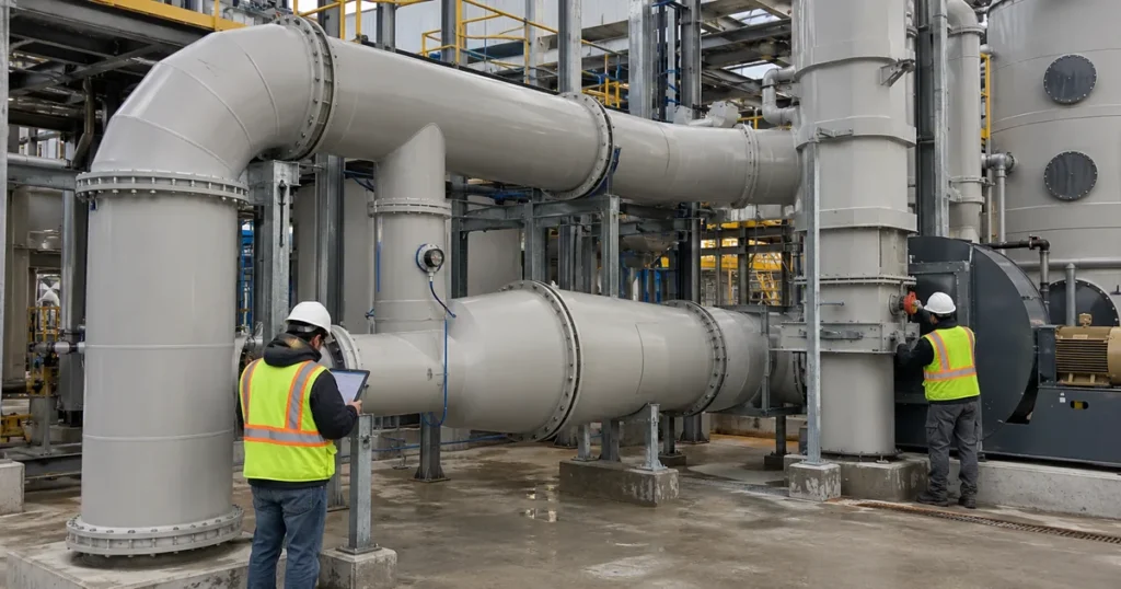
Once the system is running under an approved condition, observe the duct, supports, joints, equipment interfaces, and control components.
Look for unexpected movement, vibration, deformation, joint leakage evidence, support movement, contact with surrounding structure, abnormal noise, or a component that shifts when the fan changes state.
A condition that is invisible while the fan is off may appear under negative pressure or as equipment starts and stops.
Observation should remain qualitative unless the project defines a measurement procedure. The visible symptom is a clue that may require engineering review, not proof of one failure mechanism.
Check Drainage and Condensate Under Real Operating Conditions
A drainage path that looks correct during construction may behave differently once the process is running.
Where condensation or wet service is expected, verify that intended low points, drains, and collection paths function under the actual operating condition.
Look for liquid collecting at fittings, field joints, equipment transitions, or unintended low points.
Information
The condensate review should also consider whether the operating temperature and process condition during commissioning are representative of the service that creates condensation. A dry startup test cannot prove that a wet service condition will drain correctly later.
PDI’s condensate design resource should be used when the system requires a more detailed wet service review.
Confirm Temperature Conditions Against the Material Basis
Commissioning should record the operating temperature condition that applies to the test.
PVC and CPVC duct have different service temperature limits, and the material review should already have been completed during design. Commissioning does not redefine those limits.
The value of the commissioning temperature record is to confirm that the installed system is being evaluated under the expected operating envelope and to identify any unexpected temperature condition that requires review.
Where temperature changes materially during startup, also observe whether the installed thermal movement strategy behaves as intended.
| Commissioning Check | What to Verify | What to Record |
|---|---|---|
| Physical installation | Route, supports, joints, access, drainage, equipment interfaces | Exceptions, field changes, photographs |
| Leak testing | Approved method completed after required cure | Method, date, result, corrective action |
| Airflow controls | Blast gate and damper positions match test condition | Device position and operating mode |
| Airflow and pressure | Required branches, reference static pressure, fan condition | Measurement location, reading, test state |
| Operating environment | Make up air, room pressure, process temperature | Relevant system states and observed condition |
| Handover | Exceptions resolved or formally accepted | Final settings, retest results, approved records |
Commission More Than One Operating State When the System Requires It
A single full flow condition may not represent the most important operating case.
A branched exhaust system can behave differently when tools shut down, blast gates close, dampers modulate, process equipment changes state, or the fan control sequence adjusts speed.
The commissioning plan should identify the operating states that can materially change airflow distribution, system resistance, pressure, or equipment interface conditions.
Those states should come from the design basis. Commissioning should verify defined operating scenarios rather than inventing arbitrary combinations in the field.
Document Exceptions Before Handover
A commissioning report should clearly separate accepted conditions from unresolved exceptions.
If a branch misses airflow, a damper cannot reach its required position, a drain is inaccessible, a support has shifted, or a pressure reading differs materially from the design expectation, record the issue and its disposition.
Do not bury unresolved items in general notes.
The handover package should identify which conditions were corrected, which were accepted by the responsible project authority, and which require follow up.
This creates a baseline for future maintenance and prevents the facility from inheriting undocumented commissioning assumptions.
Build a Repeatable Handover Record
A useful commissioning record should include:
- Approved drawings and final field changes.
- Duct material and major fabricated sections.
- Test date and system operating mode.
- Fan operating condition.
- Branch states and control positions.
- Airflow measurements and locations.
- Static pressure measurements and locations.
- Make up air and relevant room pressure condition.
- Leak test method and result.
- Visible joint condition.
- Support and thermal movement observations.
- Drainage and condensate observations where applicable.
- Damper and blast gate functional checks.
- Equipment interface observations.
- Temperature condition during testing.
- Exceptions, corrective actions, and retest results.
- Final approved operating positions where relevant.
- Reference photographs and measurement point locations.
The goal is to make the final system condition reproducible.
A future engineer should be able to understand how the system was operating when it was accepted and compare later performance with the original commissioning baseline.
Commissioning Should Close the Design Loop
The design establishes the required operating conditions. Fabrication turns those requirements into duct sections and fittings. Installation places the system in the facility. Commissioning verifies whether the completed system still behaves as intended.
For PVC and CPVC industrial exhaust systems, that verification should include more than airflow.
Supports, thermal movement, field joints, control components, drainage, equipment interfaces, operating modes, fan condition, leakage, and documentation all affect whether the installed system reflects the original design basis.
A system is ready for handover when the required operating conditions have been verified, exceptions have been resolved or formally accepted, and the facility receives a clear baseline for future operation and maintenance.
Need Help Reviewing a PVC or CPVC Exhaust System Before Handover?
Send PDI the duct layout, material, sizes, process chemistry, temperatures, pressure or vacuum basis, airflow requirements, control component locations, equipment interfaces, and commissioning concerns through the Request Information form.
Have your specs ready?
PDI can help review fabrication related conditions and identify where custom duct sections or connection details may need further coordination.