Inspection Should Rebuild the Current Service Condition
A useful inspection does more than identify what looks damaged.
The purpose is to compare the system that exists today with the service condition it was originally designed to handle. That comparison matters because the duct may have changed very little while the process around it has changed substantially.
New chemicals, stronger concentrations, hotter cleaning cycles, revised fan settings, altered branch positions, longer operating hours, additional equipment, modified supports, or repeated condensate exposure can change the service condition and loading on an existing system.
PDI’s Corrosive Exhaust Duct Failure resource explains why the visible failure location is not automatically the root cause. An inspection should therefore document the physical condition and the operating history before a repair decision is made.
Start With the Operating History Before Looking at the Duct
Physical inspection is more useful when the reviewer knows what the system has experienced.
Before walking the duct route, collect the latest available process information. This should include the exhaust chemistry, normal and peak temperatures, expected pressure or vacuum, fan operating conditions, branch operating states, cleaning chemicals, shutdown practices, and any known process changes.
Maintenance history matters too. Previous joint repairs, relocated hangers, changed dampers, replaced fans, blocked drains, vibration complaints, or recurring leaks can reveal a pattern that is not obvious from one visual inspection.
Where the original drawings or fabrication records are available, compare them with the installed route. If the installed route has been modified, the inspection record should show where the current geometry differs from the design basis.
Inspect Joints for Condition, Alignment, and Evidence of Movement
Joints deserve careful attention because they connect material condition, fabrication quality, alignment, thermal movement, and local loading.
Look for visible leakage, staining, residue, separation, cracking, distortion, misalignment, or evidence that the joint is being pulled or pushed out of its intended position. A leaking joint should not automatically be classified as a joint workmanship problem.
The surrounding geometry matters. A joint near a rigid equipment connection, poorly supported fitting, thermal restraint point, or low spot can be carrying loads that originated elsewhere.
For solvent cemented, welded, flanged, or gasketed connections, inspection should follow the construction method actually used in the system. Do not assume every PVC or CPVC exhaust joint was built using the same process.
If the joint condition has changed since a previous inspection, record the direction and extent of that change. Trend information is more useful than a single photograph when movement is gradual.
Supports Should Be Checked as a System, Not One Hanger at a Time
Support condition is more than confirming that a hanger exists.
Inspect the spacing, bearing area, alignment, attachment condition, and whether the support allows or restrains the movement intended by the design. IPEX publishes PVC ventilation duct support guidance tied to size, operating temperature, heavy components, and material properties. Spears publishes separate PVC and CPVC duct support tables by size and temperature.
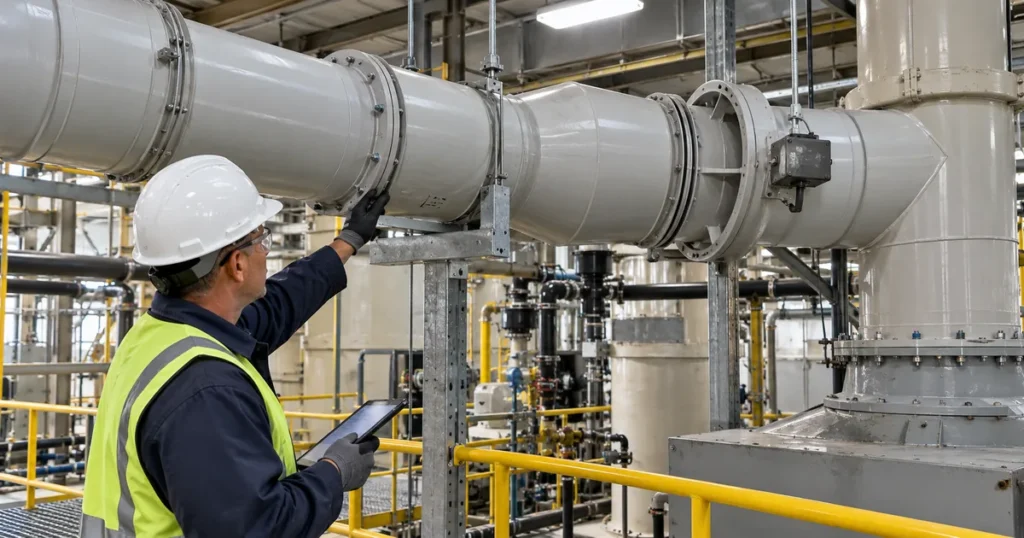
Look for sag between supports, localized flattening, abrasion, sharp bearing edges, loose hardware, shifted supports, or supports that appear to grip the duct tightly where axial movement should be available.
Concentrated components should also be checked for direct support. IPEX specifically identifies fans, hoods, scrubbers, dampers, and flanges as loads that should be supported directly rather than transferred into the duct. Blast gates and equipment transitions should also be reviewed where their weight creates a localized load.
The inspection should also look beyond one visible hanger. A local deformation can be caused by the support immediately beside it, by an excessive span, or by a load transferred from another part of the assembly.
Deformation Is a Clue That Needs Context
Sagging, flattening, ovality, distortion, or a fitting that no longer aligns with the original route should be documented carefully.
These conditions can be consistent with elevated temperature, inadequate support, concentrated load, thermal restraint, pressure or vacuum, fabrication geometry, or a combination of factors. The shape alone does not identify the cause.
Compare the observed condition with duct diameter, wall construction, operating temperature, support layout, and pressure condition. For custom fabricated or large diameter sections, include reinforcement details where they are available.
PDI’s Large Diameter PVC Duct resource explains why custom fabricated duct cannot simply inherit the assumptions used for standard extruded duct. Existing large diameter systems should be inspected against their actual construction rather than a generic duct table.
Thermal Movement Should Be Visible in the Installed Layout
PVC and CPVC change length with temperature. An inspection should verify that the installed system still has a credible movement path.
Look at expansion joints, offsets, guides, anchors, wall penetrations, equipment connections, and long straight runs. Check whether a component intended to move still has travel available and whether field modifications have unintentionally restrained it.
A support that has shifted, a flexible component that sits near the end of its travel, a joint that repeatedly moves out of alignment, or a duct section pressed against a penetration can be evidence that thermal movement is not occurring as intended.
The inspection should not assume that more restraint is the solution. Thermal movement design should distinguish ordinary supports, guides, and anchors because each has a different function.
Condensate and Low Points Need Their Own Inspection Path
Where condensation is credible, inspect the liquid path as deliberately as the airflow path.
Look for recurring wet areas, residue, blocked or damaged drains, low points, pooled liquid, staining beneath joints, corrosion of external hardware, and fittings that interrupt drainage.
Condensate can create a local liquid contact condition that differs from vapor exposure in form and contact duration. The actual liquid chemistry, temperature, and duration of contact should be reviewed where those conditions matter.
Condensate design should consider horizontal geometry, fitting orientation, drainage, support loading, and inspection access together. In an existing system, the inspection should verify whether the intended drainage path still exists after settlement, support movement, repairs, or equipment changes.
Equipment Connections and Vibration Deserve Close Attention
Connections to fans, scrubbers, hoods, stacks, and process equipment can transmit movement or vibration when the support, isolation, or interface arrangement no longer functions as intended.
Inspect connections for misalignment, movement marks, loose hardware, cracked or distorted adjacent sections, and evidence that the duct is carrying equipment load. Where flexible connectors or isolation components are part of the design, verify their visible condition and alignment using the approved maintenance procedure.
Vibration should be considered in context. A vibrating duct section may reflect fan condition, support looseness, aerodynamic excitation, equipment movement, or another source. The observation should be recorded and correlated with operating state rather than assigned a cause from appearance alone.
Blast Gates and Dampers Should Be Inspected as Functional Components
Flow control components affect more than airflow.
Inspect blast gates, butterfly dampers, gravity dampers, and similar devices for visible condition, alignment, support, accessibility, and the ability to reach the intended operating position. Where actuators or manual controls are used, confirm that the component can be operated through the approved maintenance process.
A stuck or partially positioned component can alter branch airflow and system pressure. A heavy component with inadequate support can also load adjacent duct or joints.
Record the normal operating position where it matters to the system. That information becomes valuable if airflow, pressure, or fan duty has changed since the original design.
Surface Changes Are Evidence, Not a Diagnosis
Discoloration, softening, swelling, blistering, surface etching, distortion, and cracking can be important inspection findings, but they do not all mean the same thing.
Corzan documents softening, swelling, distortion, blackening, blistering, surface etching, and cracking as possible indicators of CPVC compatibility problems under different exposure conditions. Environmental stress cracking in CPVC can involve both chemical exposure and significant mechanical stress.
Those observations are useful diagnostic clues, not proof of one failure mechanism and not a universal description of every PVC formulation. PDI’s PVC Duct Chemical Resistance resource explains why they should be compared with the actual constituents, concentration, temperature, and exposure condition.
When a surface change is found, record its location, pattern, material, nearby joint or support condition, process chemistry, temperature history, external chemical exposure, and whether the condition is progressing.
When a surface change is found, record its location, pattern, material, nearby joint or support condition, process chemistry, temperature history, external chemical exposure, and whether the condition is progressing.
Do not classify a material compatibility problem from color or texture alone.
Leakage Should Be Traced Back to the Local Load Path
Visible leakage often attracts immediate attention because it is easy to locate.
The inspection should document exactly where leakage appears and what surrounds that point. Check the joint, fitting, support, equipment connection, thermal movement path, condensate condition, and nearby deformation.
Repeated repair at the same location is especially important evidence. If a joint has been resealed or replaced multiple times, the inspection should investigate whether alignment, movement, loading, chemistry, or pressure is recreating the problem.
A repair that closes the leak without addressing the load path can leave the underlying condition unchanged.
Pressure and Vacuum Conditions Should Match the Existing Construction
An existing thermoplastic exhaust system should be reviewed against duct construction data, not pressure pipe ratings.
Record normal system static pressure and the highest credible positive or negative pressure where that information is available. Consider fan shutoff pressure where applicable, closed gates or dampers, process changes, altered branch configurations, and other operating states that can change differential pressure.
Inspect for deformation or movement that appears only during certain operating states. Where the system condition changes with fan operation, observation during approved operating conditions may provide information that a shutdown inspection cannot.
Do not prescribe a field pressure test from a generic inspection checklist. Any test method should follow the project specification, manufacturer guidance, applicable code, and facility safety requirements.
Use Repeatable Inspection Records
The value of inspection increases when the same locations can be compared over time.
Useful Information
Photograph important joints, supports, expansion components, equipment interfaces, low points, drains, and visible surface changes from repeatable viewpoints. Record the date, operating state, process condition, and approximate location.
Dimensioned observations are more useful than subjective labels where measurement is practical. Instead of recording only that a duct is sagging, document where the sag occurs and how it compares with a previous inspection or reference condition.
The inspection record should distinguish observed condition from suspected cause. That separation keeps maintenance evidence useful for later engineering review.
| Observed Condition | Possible Contributors | Verify Next |
|---|---|---|
| Joint leakage or residue | Alignment, thermal movement, local load, joining condition | Adjacent supports, movement path, chemistry, temperature, repair history |
| Sagging or distortion | Support span, temperature, concentrated load, pressure or vacuum | Support layout, operating history, duct construction, nearby equipment load |
| Recurring wet low point | Condensate, blocked drainage, geometry, settlement | Drain path, liquid chemistry, support elevation, fitting orientation |
| Cracking or surface change | Chemical exposure, external contamination, temperature, mechanical stress | Material, chemistry, temperature history, stress points, progression |
| Damper or blast gate not reaching position | Component condition, alignment, deposits, support, actuator or manual control issue | Operating position, adjacent duct alignment, support, maintenance history |
| Vibration or repeated movement | Fan condition, support looseness, aerodynamic excitation, equipment movement | Operating state, supports, equipment interface, history, nearby components |
What the Inspection Record Should Capture
A practical inspection record should identify:
- System area and duct section.
- PVC or CPVC material where known.
- Duct diameter and fabricated construction where relevant.
- Joint type and visible condition.
- Support location, bearing condition, and alignment.
- Visible sag, distortion, ovality, or movement.
- Expansion joint, guide, anchor, or offset condition.
- Condensate, wet areas, drains, and low points.
- Blast gate and damper condition and position where relevant.
- Fan, scrubber, hood, stack, and equipment interface condition.
- Visible leakage, residue, staining, or deposits.
- Surface changes such as discoloration, softening, blistering, etching, or cracking.
- Normal and unusual operating temperatures.
- Known chemistry and concentration changes.
- Normal system pressure or vacuum and relevant operating states.
- Vibration observations.
- Previous repairs or repeated problem locations.
- Photographs and comparison with prior inspection records.
- Items requiring engineering review before repair.
The goal is to create a record that another engineer can use without having to reconstruct the entire inspection from memory.
Know When Inspection Should Escalate to Engineering Review
Not every inspection finding requires replacement, and not every intact appearing section should automatically remain in service.
Escalation is appropriate when the observed condition suggests that the original service basis may no longer apply, when deformation or cracking is progressing, when chemistry or temperature has changed, when a component is repeatedly leaking, when thermal movement appears restrained, or when the system has been modified without updated design information.
At that point, the question changes from what is visible to whether the existing material, construction, and layout remain suitable for the actual operating envelope.
PDI’s failure analysis resource provides the next step when the inspection identifies a recurring or unexplained condition.
Inspection Should Support a Better Maintenance Decision
A strong PVC or CPVC duct inspection does not end with a list of defects.
It connects physical evidence to service history, geometry, supports, movement, chemistry, temperature, pressure, condensate, and equipment interfaces. That information helps the facility distinguish routine maintenance from a condition that needs engineering review or a revised fabrication detail.
The most useful inspection record is one that makes change visible. When joints, supports, wet locations, equipment connections, and surface condition are documented consistently, the facility can see whether the system is stable or whether a pattern is developing.
Need Help Reviewing an Existing PVC or CPVC Exhaust System?
Send PDI the duct material, sizes, photographs, process chemistry, temperature range, pressure or vacuum conditions, known problem areas, support layout, equipment connections, and repair history through the Request Information form.
Have your specs ready?
PDI can review the fabrication related conditions and help identify where replacement or custom sections may need to be coordinated.